b1. Design method for longitudinal reinforcements of a rectangular section in bending at the ULS, Asc and As
Eurocode 2 - Design of concrete sections
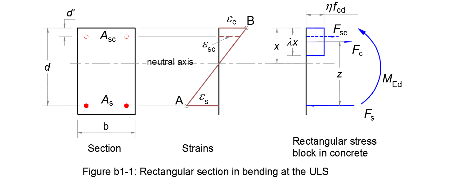
Assumptions
1. Plane sections remain plane after straining, so that there is a linear distribution of strains across the section.
2. Reinforcing steels have the same deformation as the nearby concrete.
3. The tensile strength of concrete is ignored.
4. A rectangular distribution of the compressive stress in the concrete is assumed, see 3.1.7 (3).
5. The ultimate limit state occurs when the strain in the reinforcing steel reaches the limit εud (Pivot A) and/or the strain in the concrete reaches the limit εcu3 (Pivot B).
Considering the depth of the neutral axis/the effective depth of the cross-section:
| αu = x/d | (b1.1) |
The linear distribution of strains gives:
| αu = εc/(εc + εs) | (b1.2) |
Balanced section AB
We consider a balanced section for which the Pivot A and Pivot B are reached at the same time: εc = εcu3 and εs = εud.
For the balanced section, calculating:
| αAB = εcu3/(εcu3 + εud) | (b1.3) |
If αu > αAB ⇔ the Pivot B is reached first. Otherwise, the Pivot A is reached first.
Yield tensile steel section
At the beginning of the top branch of the design stress-strain diagram for reinforcing steel (see Figure 3.8), the strain of steel is equal to εse = fyd/Es.
Calculating:
| αse = εcu3/(εcu3 + εse) | (b1.4) |
If αu > αse ⇔ the steel does not reach yield. In this case, the design is not economical. Therefore, a compressive reinforcement should be designed.
If αu ≤ αse, no compressive reinforcement is needed.
Singly reinforced section
For equilibrium, the ultimate design moment must be balanced by the moment of resistance of the section:
| MEd = Fc z = b η fcd λ x (d - λ x/2) | (b1.5) |
| MEd = Fs z = As σs (1 - λ αu /2) d ⇔ As = MEd /[(1 - λ αu /2) d σs] | (b1.6) |
Substituting the following in (b1.5):
| μu = MEd /(b d2 η fcd) | (b1.7) |
(b1.5) ⇒ 2 μu = 2 λ (x/d) - λ2 (x/d)2
|
⇔ 2 μu = 2 λ (αu) - λ2 (αu)2 |
(b1.8) |
If μu ≤ 0,5, this quadratic equation has a solution:
| αu = [1 - (1 - 2μu)0.5] /λ | (b1.9) |
• αu ≤ αAB ⇒ Pivot A, no compressive reinforcement is needed
The strain in the tensile reinforcement εs = εud.
By reading the design stress-strain diagram for reinforcing steel (see more in 3.2.7 (2))
⇒ the stress in the tensile reinforcement σs.
(b1.6) ⇒ the tensile reinforcement As.
• αAB < αu ≤ αse ⇒ Pivot B, the tensile reinforcement has reached yield, no compressive reinforcement is needed
The strain in the concrete εc = εcu3.
The strain in the tensile reinforcement:
| εs = εcu3⋅(d - x)/x = εcu3⋅(1 - αu)/αu | (b1.10) |
By reading the design stress-strain diagram for reinforcing steel
⇒ the stress in the tensile reinforcement σs.
(b1.6) ⇒ the tensile reinforcement As.
If μu > 0,5, the quadratic equation (b1.8) does not have a solution.
In this case, we consider that the singly reinforced section is not suitable because the bending moment is too big. A compressive reinforcement should be calculated.
Doubly reinforced section
• αu > αse ⇒ Pivot B, tensile reinforcement does not reach yield, compressive reinforcement is needed;
• Or μu > 0,5
Considering that the section is an overlap of two fictive sections (see Figure b1-2):
- One concrete section with only a tensile reinforcement As1 that has a strain εs = εse = fyd/Es;
- One section with only two reinforcements As2 and Asc.
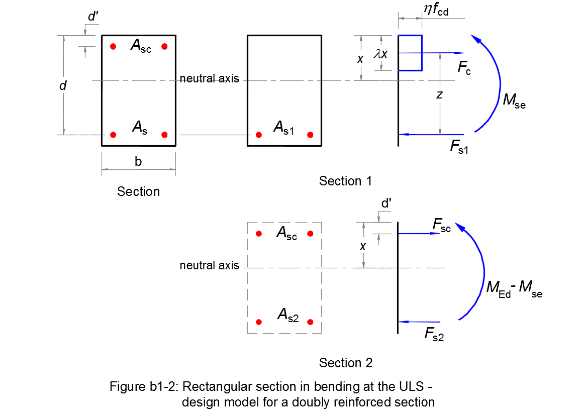
For the first section:
(b1.4) ⇒ αse; (b1.8) ⇒ μse.
(b1.7) ⇒ the bending moment supported by this section:
| Mse = μse (b d2 η fcd) | (b1.11) |
(b1.6) ⇒ the tensile reinforcement As1 = Mse /[(1 - λ αse /2) d fyd].
For the second section, at equilibrium:
| MEd - Mse = Asc (d - d') σsc ⇔ Asc = (MEd - Mse) /[(d - d') σsc] | (b1.12) |
| Fs2 = Fsc ⇔ As2 = Asc σsc /σs2 | (b1.13) |
The strain diagram ⇒ the strain in the compression reinforcement
εsc = εcu3⋅(αse - d/d')/αse.
By reading the design stress-strain diagram for reinforcing steel
⇒ the stress in the compressive reinforcement σsc.
(b1.12) ⇒ the compressive reinforcement Asc.
σs2 = σs1 = fyd
(b1.13) ⇒ the tensile reinforcement As2.
Finally, the total tensile reinforcement is:
| As = As1 + As2 | (b1.14) |
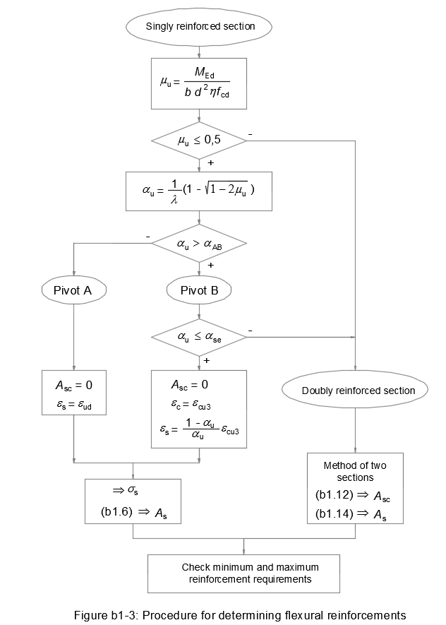
Flowchart
Figure b1-3 resumes this design method for a rectangular reinforced concrete section in bending: