Stress in reinforcing steel depending on its strain, σs
Eurocode 2 part 1-1: Design of concrete structures 3.2.7 (2)
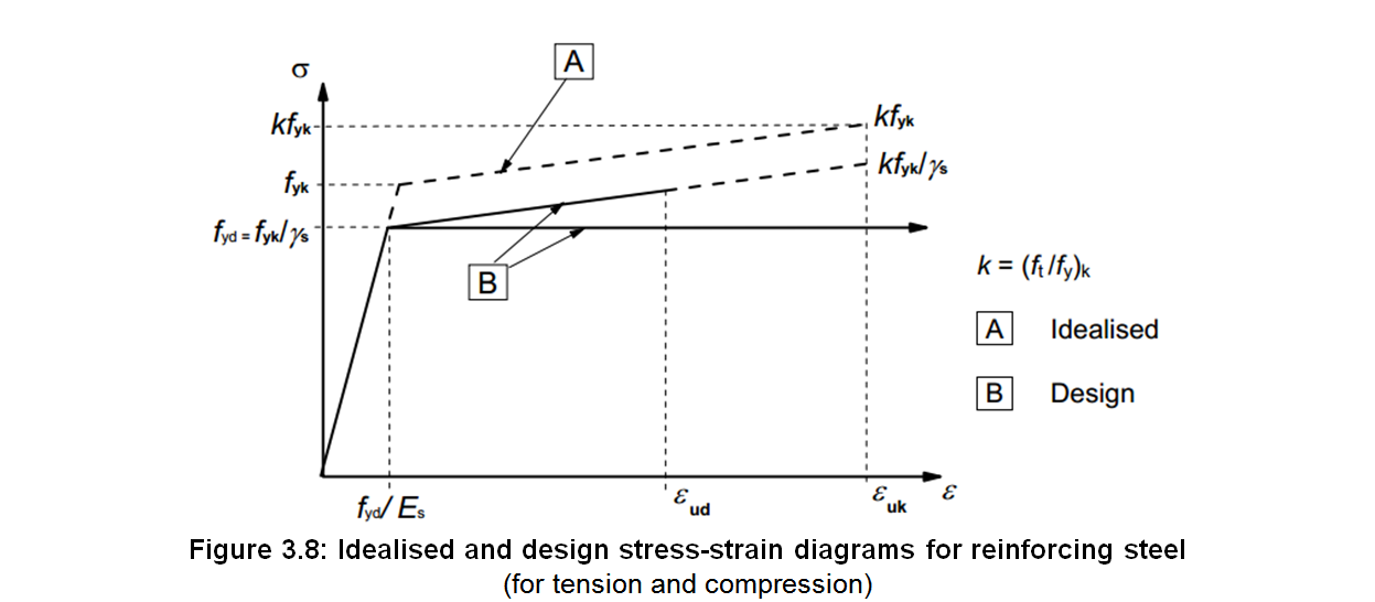
For normal design, either of the following assumptions may be made (see Figure 3.8):
a) an inclined top branch with a strain limit of εud and a maximum stress of kfyk/γS at εuk, where k = (ft/fy)k,
b) a horizontal top branch without the need to check the strain limit.
where:
- fyk
- is the characteristic yield strength of the reinforcing steel, see § 3.2.2 (3)P.
- γS
- is the partial factor for reinforcing steel, see § 2.4.2.4 (1).
- k
- is the ductility property, see Table C.1
- εuk
- is the characteristic strain of the reinforcing steel at maximum load, see Table C.1
- Es
- is the design value of the modulus of elasticity of the reinforcing steel, see § 3.2.7 (4).
- fyd
- is the design yield strength of the reinforcing steel, fyd = fyk/γS
- εud
- is the design strain of the reinforcing steel at maximum load, εud = Coef(εud)⋅εuk, see § 3.2.7 (2) for the value of Coef(εud).
If εs ≤ εse (with εse = fyd/Es), the stress in reinforcing steel σs = Es⋅εs.
If εse < εs ≤ εud, the stress in reinforcing steel σs is equal to:
- fyd + (εs - εse)⋅(kfyk - fyk)/(εuk - fyk/Es) for inclined top branch,
- fyd for horizontal top branch.
This application calculates the stress in reinforcing steel σs from your inputs. Intermediate results will also be given.
