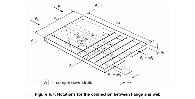
Shear between web and flanges: the transverse reinforcement per unit length Asf/sf and crushing of the compressive structs in the flanges
Eurocode 2 part 1-1: Design of concrete structures 6.2.4 (3)

• The transverse reinforcement per unit length, Asf/sf, may be determined as follows (see Figure 6.7):
| (Asf⋅fyd / sf) ≥ vEd⋅hf / cotθf | (6.21) |
where:
- vEd
- is the longitudinal shear stress at the junction between one side of a flange and the web. It is determined by the change of the normal (longitudial) force in the part of the flange considered:
vEd = ΔFd / (hf⋅Δx) (6.20) with
- hf
- the thickness of flange at the junctions
- Δx
- the length under consideration.
The maximum value that may be assumed for Δx is half the distance between the section where the moment is 0 and the section where the moment is maximum. Where point loads are applied the length Δx should not exceed the distance between point loads - ΔFd
- the change of the normal force in the flange over the length Δx.
- θf
- is the angle between the concrete compression strut and the beam axis, see § 6.2.4 (4)
- fyd
- is the design yield strength of the reinforcement, fyd = fyk/γS,
see § 2.4.2.4 (1), § 2.4.2.4 (2) for the values of γS,
see § 3.2.2 (3)P for the uper limit of fyk,
see Figure 3.8 for the design stress-strain diagrams of the reinforcing steel.
• To prevent crushing of the compression struts in the flange, the following condition should be satisfied:
| vEd ≤ ν fcd sinθf cosθf | (6.22) |
where:
- ν
- is a strength reduction factor for concrete cracked in shear, the recommended value of ν is ν = 0,6(1 - fck/250) (Expression 6.6N in § 6.2.2 (6))
- fcd
- is the design compressive strength of concrete, see § 3.1.6 (1)P.
This application calculates the reinforcement per unit length Asf/sf from your inputs. Intermediate results will also be given.
