Longitudinal reinforcements of a rectangular section in bending at the ULS, Asc and As
Eurocode 2 - Design of concrete sections Method b1
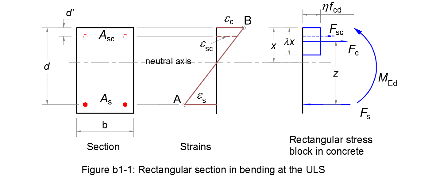
The reinforcements of a rectangular section in bending at the ultimate limit state are calculated according to method b1.
The parameters needed for the design are the followings:
- •
- Steel class: see Table C.1. The characteristic strain εuk and the ductility property k will be taken equal to their minimum values in the table;
- Es
- is the design value of the modulus of elasticity of the reinforcing steel, see § 3.2.7 (4);
- fyk
- is the yield strength of the reinforcing steel, see § 3.2.2 (3)P;
- γs
- is the partial factor for reinforcing steel at the ultimate limit state, see § 2.4.2.4 (1);
- •
- Steel diagram: is the design stress-strain diagram for reinforcing steel, from which the design strain limit εud and the stress in the steel will be defined. See § 3.2.7 (2) and application stress-strain for reinforcing steel;
- •
- Coef(εud/εuk): is chosen by National Annex, see § 3.2.7 (2);
- •
- Concrete class: see Table 3.1;
- fcd
- is the design compressive strength of concrete, see application;
- b
- is the width of the concrete cross-section;
- d
- is the effective depth of the concrete cross-section;
- d'
- is the distance from the compression fibre to the centre of gravity of the compression steel;
- MEd
- is the design bending moment at the ultimate limit state.
The calculated reinforcements should be compared to the minimum and maximum reinforcement requirements for members (slabs, beams, foundations...). Such verification is outside scope of this application.
This application calculates the reinforcements As, Asc from your inputs. Intermediate results will also be given.
