Ultimate moment of resistance of a rectangular section in bending, MRd
Eurocode 2 - Design of concrete sections Method b3
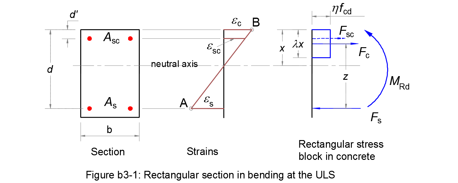
The ultimate moment of resistance of a rectangular section in bending at the ULS are calculated according to method b3.
The parameters needed for the design are the followings:
- •
- Steel class: see Table C.1. The characteristic strain εuk and the ductility property k will be taken equal to their minimum values in the table;
- Es
- is the design value of the modulus of elasticity of the reinforcing steel, see § 3.2.7 (4);
- fyk
- is the yield strength of the reinforcing steel, see § 3.2.2 (3)P;
- γs
- is the partial factor for reinforcing steel at the ultimate limit state, see § 2.4.2.4 (1);
- •
- Steel diagram: is the design stress-strain diagram for reinforcing steel, from which the design strain limit εud and the stress in the steel will be defined. See § 3.2.7 (2) and application stress-strain for reinforcing steel;
- •
- Coef.(εud/εuk): is chosen by National Annex, see § 3.2.7 (2);
- •
- Concrete class: see Table 3.1;
- fcd
- is the design compressive strength of concrete, see application;
- b
- is the width of the concrete cross-section;
- d
- is the effective depth of the concrete cross-section;
- d'
- is the distance from the compression fibre to the centre of gravity of the compression steel;
- As
- is the cross sectional area of the tensile reinforcement;
- Asc
- is the cross sectional area of the compression reinforcement.
This application calculates the ultimate moment of resistance MRd from your inputs. Intermediate results will also be given.
