b12. Calculation method for stresses of a T-section in bending at the SLS, σc and σs
Eurocode 2 - Design of concrete sections
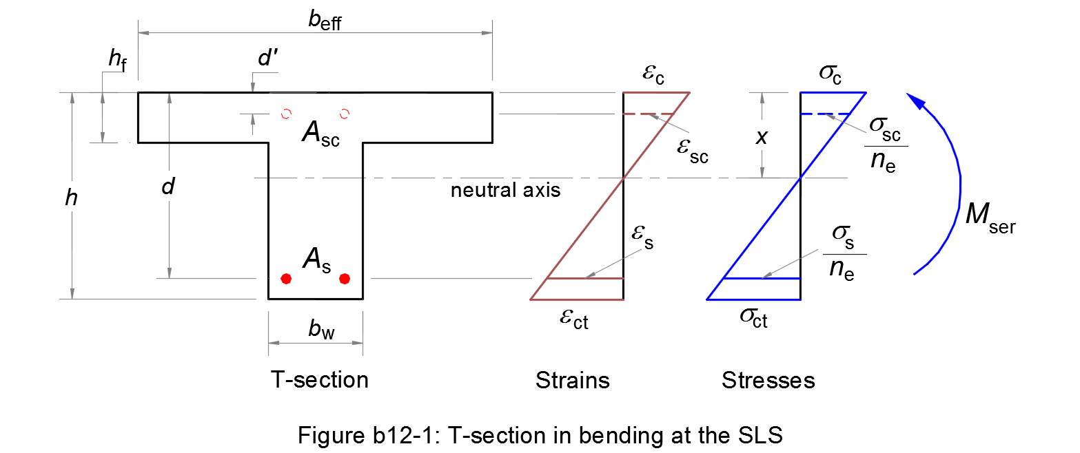
Geometrical properties of the section
First of all, the concrete section must be verified if it is cracked by comparing the bending moment Mser with the moment of resistance Mct,ser according to method b7.
Case of uncracked section
The area of the homogeneous section, the depth of the neutral axis and the second moment of the homogeneous section are respectively calculated as follows:
| Ac,eq = bw h + (beff - bw) hf + ne (As + Asc) | (b12.1) |
| x = [(bw h2)/2 + (beff - bw) hf2/2 + ne (As d + Asc d')] / Ac,eq | (b12.2) |
| Ic,eq = (bw h3)/3 + (beff - bw) hf3/3 + ne (As d2 + Asc d'2) - Ac,eq x2 | (b12.3) |
Case of cracked section
The tensile concrete below the neutral axis is ignored. If the neutral axis is in the flange, the geometrical properties of the T-section are respectively calculated as follows:
| Ac,eq = beff x + ne (As + Asc) | (b12.4) |
| x = [(beff x2)/2 + ne (As d + Asc d')] / Ac,eq | (b12.5) |
| Ic,eq = (beff x3)/3 + ne (As d2 + Asc d'2) - Ac,eq x2 | (b12.6) |
Substituting Ac,eq in (b12.5) by (b12.4), (b12.5) becomes a quadratic equation of x. The depth of the neutral axis x is obtained by resolving this equation.
If x ≤ hf, the neutral axis is in the flange of the T-section.
If x > hf, the neutral axis is in the web of the T-section. The geometrical properties of the T-section are respectively calculated as follows:
| Ac,eq = bw x + (beff - bw) hf + ne (As + Asc) | (b12.7) |
| x = bw x2 /2 + [(beff - bw) hf2 /2 + ne (As d + Asc d')] / Ac,eq | (b12.8) |
| Ic,eq = bw x3 /3 + (beff - bw) hf3 /3 + ne (As d2 + Asc d'2) | (b12.9) |
The depth of the neutral axis x is obtained by resolving the quadratic equation from (b12.7) and (b12.8).
Calculation of stresses
As the case may be, the second moment of area of the homogeneous section Ic,eq is determined by (b12.3), (b12.6) or (b12.9). The maximum compressive stress in the concrete and the tensile stress in the reinforcement are respectively calculated as follows:
| σc = Mser x / Ic,eq | (b12.10) |
| σs = Mser (d - x) / Ic,eq | (b12.11) |
where:
- Mser
- is the design bending moment at the serviceability limit state.
If needed, the compressive stress in the reinforcement is equal to:
| σsc = Mser (x - d') / Ic,eq | (b12.12) |
If Mser is generated by the characteristic combination of loads, the stresses may be used to verify the stress limitation, see § 7.2 (2) and § 7.2 (5) for critical values chosen by country.
If Mser is generated by the quasi-permanent combination of loads, the tensile stress in the reinforcement may be used to calculate the crack width of a cracked section.
