b10. Design method for tensile reinforcement of a rectangular section in bending at the SLS with known compressive reinforcement, As
Eurocode 2 - Design of concrete sections
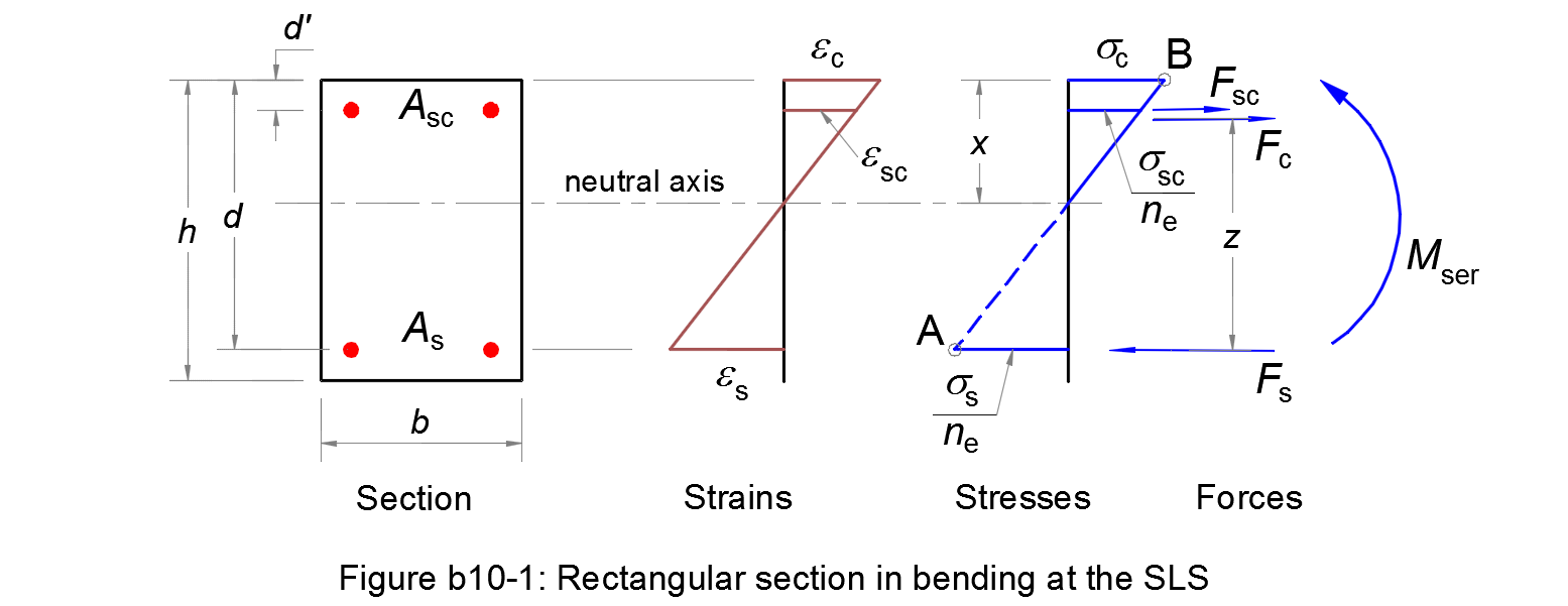
Assumptions
1. Plane sections remain plane after straining, so that there is a linear distribution of strains across the section.
2. Reinforcing steels have the same deformation as the nearby concrete.
3. The tensile strength of concrete is ignored.
4. A triangular distribution of the compressive stress in the concrete is assumed.
5. The serviceability limit state occurs when the tensile stress in the reinforcement reaches the limit σs,ser = k3 fyk (Pivot A) and/or the compressive stress in the concrete reaches the limit σc,ser = k1 fck (Pivot B). The parameters k1 and k3 are chosen by National Annex, see § 7.2 (2) and § 7.2 (5) respectively.
Considering the depth of the neutral axis/the effective depth of the cross-section:
| αser = x/d | (b10.1) |
The linear distribution of strains and the stress diagram gives:
| αser = εc/(εc + εs) = ne σc/(ne σc + σs) | (b10.2) |
where:
- ne
-
is the effective modular ratio
ne = Es / Ec,effwith:
- Es
- the design value of the modulus of elasticity of the reinforcing steel, see § 3.2.7 (4)
- Ec,eff
- the effective modulus of elasticity for concrete.
Balanced section AB
We consider a balanced section for which the Pivot A and Pivot B are reached at the same time: σs = σs,ser and σc = σc,ser.
For the balanced section, calculating:
| αAB = ne σc,ser/(ne σc,ser + σs,ser) | (b10.3) |
If αser > αAB ⇔ the Pivot B is reached first. Otherwise, the Pivot A is reached first.
Serviceability limit state at Pivot B
For equilibrium, the ultimate design moment must be balanced by the moment of resistance of the section:
| Mser = Fc z = 0,5 b σc,ser x (d - x/3) = 0,5 b d2 σc,ser αc,ser (1 - αc,ser/3) | (b10.4) |
Substituting the following in (b10.4):
| μc,ser = Mser /(b d2 σc,ser) | (b10.5) |
(b10.4) ⇒ μc,ser = 0,5 αc,ser ( 1 - αc,ser/3)
| ⇔ αc,ser2 - 3 αc,ser + 6 μc,ser = 0 | (b10.6) |
If μc,ser ≤ 0,375, this quadratic equation has a solution:
| αc,ser = 1,5 [1 - (1 - 8 μc,ser/3)0.5] | (b10.7) |
Serviceability limit state at Pivot A
For equilibrium, the ultimate design moment must be balanced by the moment of resistance of the section:
| Mser = Fc z = 0,5 b σc x (d - x/3) = 0,5 b d2 σc αs,ser (1 - αs,ser/3) | (b10.8) |
The stress σc is deducted from the stress diagram:
| σc = σs,ser αs,ser /[ne (1 - αs,ser)] | (b10.9) |
Calculating:
| μs,ser = Mser /(b d2 σs,ser) | (b10.10) |
Substituting (b10.9) and (b10.10) in (b10.8),
(b10.8) ⇒ μs,ser = 0,5 ne αs,ser2 ( 1 - αs,ser/3)
| ⇔ αs,ser3 - 3 αs,ser2 - 6 ne μs,ser αs,ser + 6 ne μs,ser = 0 | (b10.11) |
By solving this cubic equation, we get a root αs,ser ∈ (0, 1).
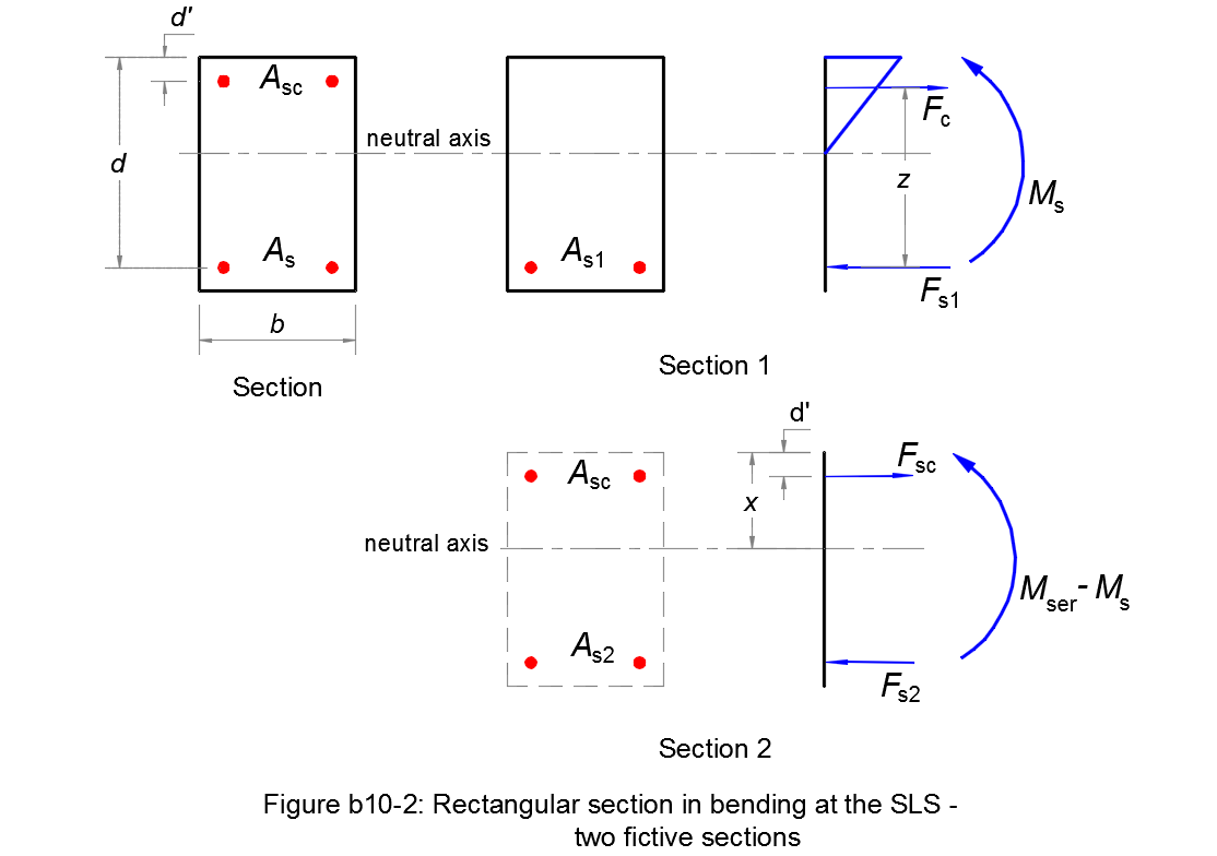
Two fictive sections
Considering that the section is an overlap of two fictive sections (see Figure b10-2):
- One concrete section with only a tensile reinforcement As1;
- One section with only two reinforcements As2 and Asc.
Iterative calculation of the stress σsc
Assumimg the stress in the compressive reinforcement σsc = fyd = fyk/γs.
The bending moment Ms supported by the section without compression reinforcement:
| Ms = Mser - Asc σsc (d - d') | (b10.12) |
Hence:
| μc,ser = Ms /(b d2 σc,ser) |
| αc,ser = 1,5 [1 - (1 - 8 μc,ser/3)0.5] |
• αc,ser ≤ αAB ⇒ Pivot A
| μs,ser = Ms /(b d2 σs,ser) |
| (b10.11) ⇒ αs,ser |
Considering αser = αs,ser.
The stress diagram ⇒ the compressive stress:
| σsc* = σs,ser (αser - d'/d)/(1 - αser) | (b10.13) |
• αu > αAB ⇒ Pivot B
Considering αser = αc,ser.
The stress diagram ⇒ the compressive stress:
| σsc* = ne σc,ser (αser - d'/d)/αser | (b10.14) |
This calculated value of σsc* must be compared with the initial value σsc. If the difference is greater than 5 %, we start over with a lower value of σsc. If the difference is lower than or equal to 5 %, we accept the initial value σsc as the stress in the compressive reinforcement.
Reinforcement As
For the first fictive section without compression steel, the tensile stress in the reinforcement σs is equal to σs,ser in case of Pivot A, is equal to ne σc,ser (1 - αser)/αser in case of Pivot B.
The tensile reinforcement As1:
| As1 = Ms /[(1 - αser /3) d σs] | (b10.15) |
The second fictive section at equilibrium gives the tensile reinforcement As2:
| As2 = Asc σsc /σs | (b10.16) |
Finally, the total tensile reinforcement is:
| As = As1 + As2 | (b10.17) |
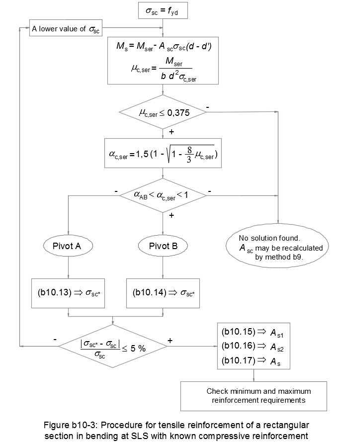
Flowchart
Figure b10-3 resumes this design method for a rectangular reinforced concrete section in bending at the SLS with known compressive reinforcement: