b11. Calculation method for moment of resistance of a rectangular section in bending at the SLS by stress limitation, Mser
Eurocode 2 - Design of concrete sections
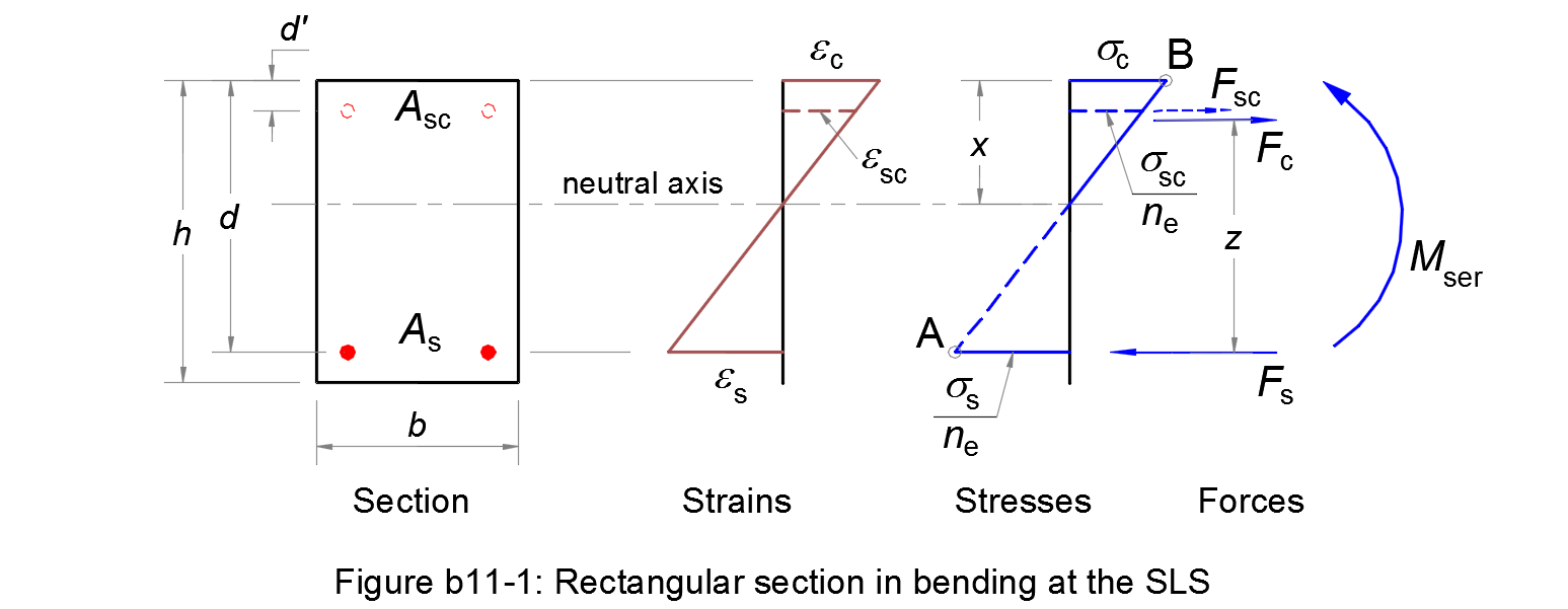
Assumptions
1. Plane sections remain plane after straining, so that there is a linear distribution of strains across the section.
2. Reinforcing steels have the same deformation as the nearby concrete.
3. The tensile strength of concrete is ignored.
4. A triangular distribution of the compressive stress in the concrete is assumed.
5. The serviceability limit state occurs when the tensile stress in the reinforcement reaches the limit σs,ser = k3 fyk (Pivot A) and/or the compressive stress in the concrete reaches the limit σc,ser = k1 fck (Pivot B). The parameters k1 and k3 are chosen by National Annex, see § 7.2 (2) and § 7.2 (5) respectively.
Considering the depth of the neutral axis/the effective depth of the cross-section:
| αser = x/d | (b11.1) |
The linear distribution of strains and the stress diagram gives:
| αser = εc/(εc + εs) = ne σc/(ne σc + σs) | (b11.2) |
where:
- ne
-
is the effective modular ratio
ne = Es / Ec,effwith:
- Es
- the design value of the modulus of elasticity of the reinforcing steel, see § 3.2.7 (4)
- Ec,eff
- the effective modulus of elasticity for concrete.
Balanced section AB
We consider a balanced section for which the Pivot A and Pivot B are reached at the same time: σs = σs,ser and σc = σc,ser.
For the balanced section, calculating:
| αAB = ne σc,ser/(ne σc,ser + σs,ser) | (b11.3) |
If αser > αAB ⇔ the Pivot B is reached first. Otherwise, the Pivot A is reached first.
Compression depth ratio αser
The stress diagram ⇒ the compressive stresses in the reinforcement the concrete are respectively calculated as follows:
| σsc = σs (αser - d'/d) /(1 - αser) | (b11.4) |
| σc = (σs /ne)⋅αser /(1 - αser) | (b11.5) |
For equilibrium, the sum of forces acting on the section gives:
| Fs = Fsc + Fc | |
| ⇔ As σs = Asc σsc + 0,5 b d αser σc | (b11.6) |
Substituting (b11.4) and (b11.5) in (b11.6), (b11.6) becomes a quadratic equation of αser:
| b d αser2 + 2 ne (As + Asc) αser - 2 ne (As + Asc d' /d) | (b11.7) |
Comparing the root αser ∈ (d'/d, 1) of this equation with the balanced value αAB.
• αser ≤ αAB ⇒ Pivot A
The tensile stress in the reinforcement σs = σs,ser.
The compressive stresses in the reinforcement and the concrete are respectively calculated according to (b11.4) and (b11.5).
• αser > αAB ⇒ Pivot B
The compressive stress in the concrete σc = σc,ser.
The stress diagram ⇒ the tensile stress in the reinforcement and the compressive stress in the reinforcement are respectively calculated as follows:
| σs = ne σc,ser (1 - αser) /αser | (b11.8) |
| σsc = ne σc,ser (αser - d'/d) /αser | (b11.9) |
Serviceability moment of resistance Mser
For equilibrium, the sum of moments to the centre of gravity of the tensile reinforcement allows the calculation of the moment of resistance:
| Mser = Asc σsc (d - d') + 0,5 b d2 αser (1 - αser /3) σc | (b11.10) |
