b4. Design method for longitudinal reinforcements of a T-section in bending at the ULS, Asc and As
Eurocode 2 - Design of concrete sections
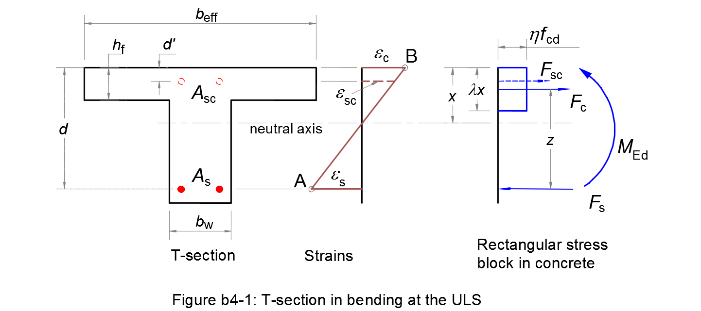
Assumptions
1. Plane sections remain plane after straining, so that there is a linear distribution of strains across the section.
2. Reinforcing steels have the same deformation as the nearby concrete.
3. The tensile strength of concrete is ignored.
4. A rectangular distribution of the compressive stress in the concrete is assumed, see 3.1.7 (3).
5. The ultimate limit state occurs when the strain in the reinforcing steel reaches the limit εud (Pivot A) and/or the strain in the concrete reaches the limit εcu3 (Pivot B).
Reference moment MTu
The moment balanced by the compressive flange is given by:
| MTu = beff hf η fcd (d - hf/2) | (b4.1) |
If MEd ≤ MTu, the compressive stress block lies within the compression flange. Because the tensile concrete is ignored, the T-section can be considered as an equivalent rectangular section of breadth beff. The method b1 is applied to calculate longitudinal reinforcements As & Asc of this section.
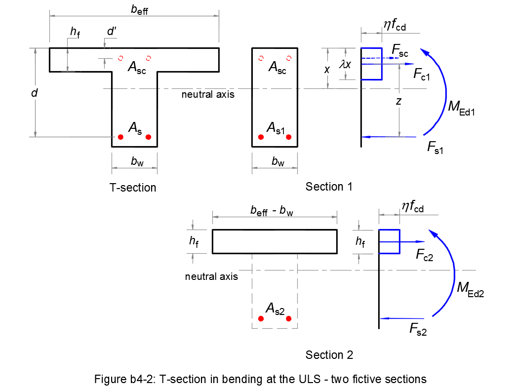
If MEd > MTu, the compressive stress block extends below the flange. the T-section can be considered as two fictive sections (see Figure b4.2).
Two fictive sections
-
The first fictive section is a rectangular section bw x d
that balances a fraction MEd1 of the total moment MEd:
The method b1 is applied to calculate longitudinal reinforcements As1 & Asc of this section.MEd1 = MEd - MEd2 (b4.2) -
The second fictive section is a T-section of flange width beff - bw
and zero web width.
This section balances a moment MEd2:
MEd2 = (beff - bw) hf η fcd (d - hf/2) (b4.3)
From the calculation of the first fictive section, we get the stress in the tensile reinforcement σs. For equilibrium of the second section, the tensile reinforcement As2 is determined as:
| As2 = (beff - bw) hf η fcd / σs | (b4.5) |
The total tensile reinforcement As is given by:
| As = As1 + As2 | (b4.6) |
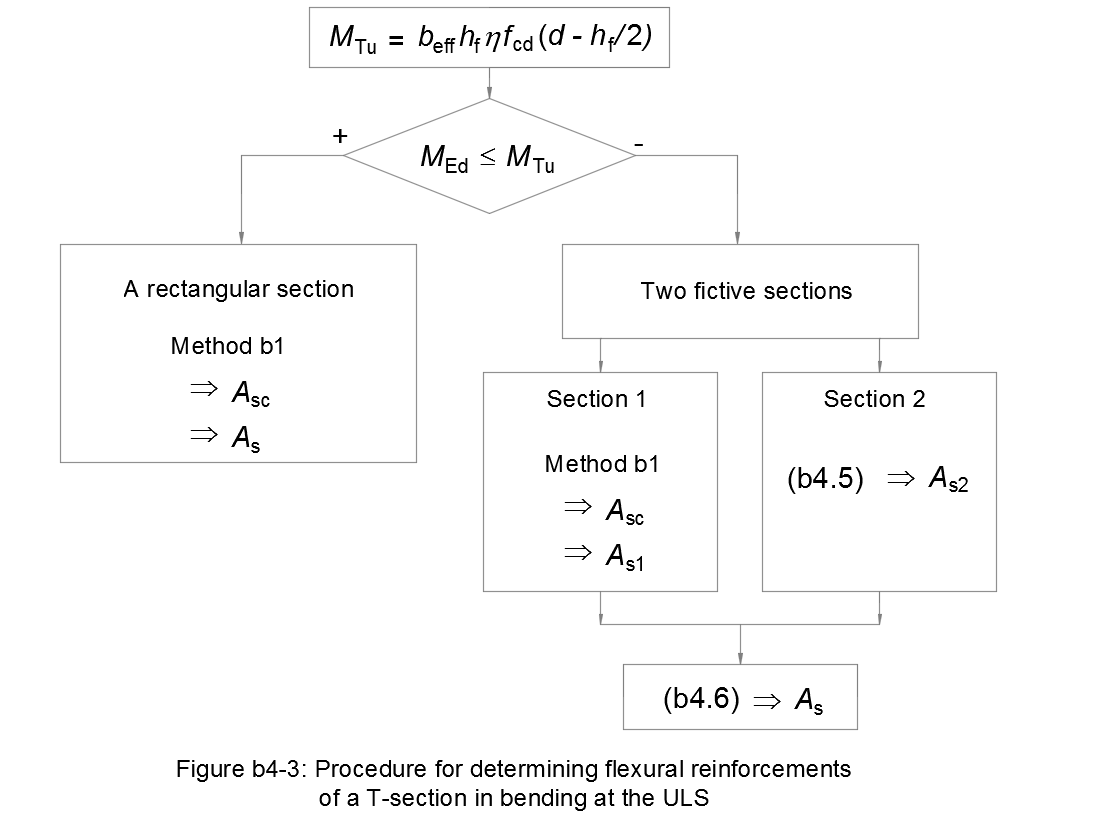
Flowchart
Figure b4-3 resumes this design method for reinforcements of a T-section in bending at ULS: