b9. Design method for longitudinal reinforcements of a rectangular section in bending at the SLS, Asc and As
Eurocode 2 - Design of concrete sections
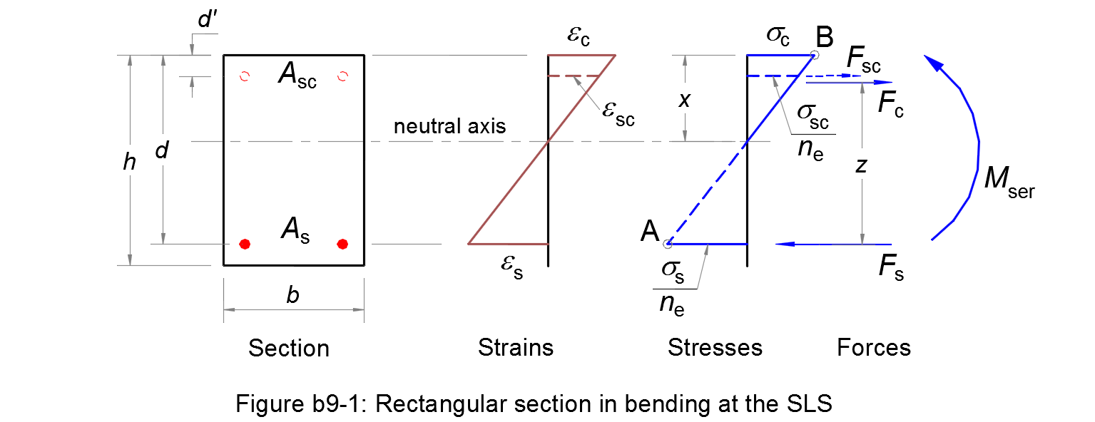
Assumptions
1. Plane sections remain plane after straining, so that there is a linear distribution of strains across the section.
2. Reinforcing steels have the same deformation as the nearby concrete.
3. The tensile strength of concrete is ignored.
4. A triangular distribution of the compressive stress in the concrete is assumed.
5. The serviceability limit state occurs when the tensile stress in the reinforcement reaches the limit σs,ser = k3 fyk (Pivot A) and/or the compressive stress in the concrete reaches the limit σc,ser = k1 fck (Pivot B). The parameters k1 and k3 are chosen by National Annex, see § 7.2 (2) and § 7.2 (5) respectively.
Considering the depth of the neutral axis/the effective depth of the cross-section:
| αser = x/d | (b9.1) |
The linear distribution of strains and the stress diagram gives:
| αser = εc/(εc + εs) = ne σc/(ne σc + σs) | (b9.2) |
where:
- ne
-
is the effective modular ratio
ne = Es / Ec,effwith:
- Es
- the design value of the modulus of elasticity of the reinforcing steel, see § 3.2.7 (4)
- Ec,eff
- the effective modulus of elasticity for concrete.
Balanced section AB
We consider a balanced section for which the Pivot A and Pivot B are reached at the same time: σs = σs,ser and σc = σc,ser.
For the balanced section, calculating:
| αAB = ne σc,ser/(ne σc,ser + σs,ser) | (b9.3) |
If αser > αAB ⇔ the Pivot B is reached first. Otherwise, the Pivot A is reached first.
Serviceability limit state at Pivot B
For equilibrium, the ultimate design moment must be balanced by the moment of resistance of the section:
| Mser = Fc z = 0,5 b σc,ser x (d - x/3) = 0,5 b d2 σc,ser αc,ser (1 - αc,ser/3) | (b9.4) |
Substituting the following in (b9.4):
| μc,ser = Mser /(b d2 σc,ser) | (b9.5) |
(b9.4) ⇒ μc,ser = 0,5 αc,ser ( 1 - αc,ser/3)
| ⇔ αc,ser2 - 3 αc,ser + 6 μc,ser = 0 | (b9.6) |
If μc,ser ≤ 0,375, this quadratic equation has a solution:
| αc,ser = 1,5 [1 - (1 - 8 μc,ser/3)0.5] | (b9.7) |
Serviceability limit state at Pivot A
For equilibrium, the ultimate design moment must be balanced by the moment of resistance of the section:
| Mser = Fc z = 0,5 b σc x (d - x/3) = 0,5 b d2 σc αs,ser (1 - αs,ser/3) | (b9.8) |
The stress σc is deducted from the stress diagram:
| σc = σs,ser αs,ser /[ne (1 - αs,ser)] | (b9.9) |
Calculating:
| μs,ser = Mser /(b d2 σs,ser) | (b9.10) |
Substituting (b9.9) and (b9.10) in (b9.8),
(b9.8) ⇒ μs,ser = 0,5 ne αs,ser2 ( 1 - αs,ser/3)
| ⇔ αs,ser3 - 3 αs,ser2 - 6 ne μs,ser αs,ser + 6 ne μs,ser = 0 | (b9.11) |
By solving this cubic equation, we get a root αs,ser ∈ (0,1).
• αc,ser > αAB ⇒ Pivot B
The tensile reinforcement As may be determined in two ways:
- Based solely on the Pivot B and no compressive reinforcement will be provided;
- Based on the balanced section AB. Thus, the tensile reinforcement As is optimized because its stress σs is taken equal to the limit σs,ser. This optimization requires a calculation of the compressive reinforcement Asc.
In the first case, the tensile stress in the reinforcement is deducted from the stress diagram:
| σs = ne σc,ser (1 - αc,ser) /αc,ser | (b9.12) |
The equilibrium of the section allows the calculation of the tensile reinforcement:
| As = Mser / [σs d (1 - αc,ser/3)] | (b9.13) |
In the second case, we consider that the section is an overlap of two fictive sections (see Figure b9-2):
- One concrete section with only a tensile reinforcement As1 This section reaches the Pivot A and Pivot B at the same time (balanced section).
- One section with only two reinforcements As2 and Asc.
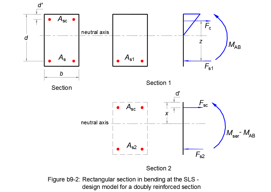
The bending moment supported by the first section is equal to:
| MAB = 0,5 b d2 αAB σc,ser (1 - αAB/3) | (b9.14) |
The tensile reinforcement As1 of the first section:
| As1 = MAB /[σs,ser d (1 - αAB/3)] | (b9.15) |
The tensile reinforcement As2 of the second section:
| As2 = (Mser - MAB) /[σs,ser (d - d')] | (b9.16) |
The compressive stress in the reinforcement:
| σsc = σs,ser [αAB - d'/d) /(1 - αAB)] | (b9.17) |
The compressive reinforcement As2:
| Asc = As2 σs,ser /σsc | (b9.18) |
Finally, the total tensile reinforcement is equal to:
| As = As1 + As2 | (b9.19) |
• αc,ser ≤ αAB ⇒ Pivot A
No compressive reinforcement is needed.
The tensile reinforcement is calculated using αs,ser from (b9.11):
| As = Mser /[σs,ser d (1 - αs,ser/3)] | (b9.20) |
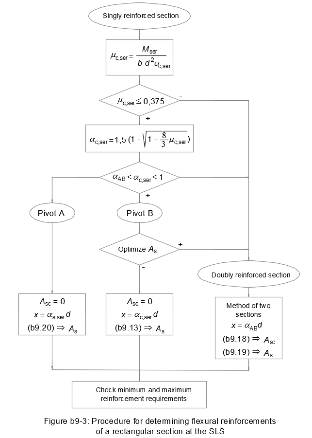
Flowchart
Figure b9-3 resumes this design method for a rectangular reinforced concrete section in bending at the serviceability limit state: